Project Home
H1 Prototype
Mechanicals
|
Heliostat Mechanicals - Geometry
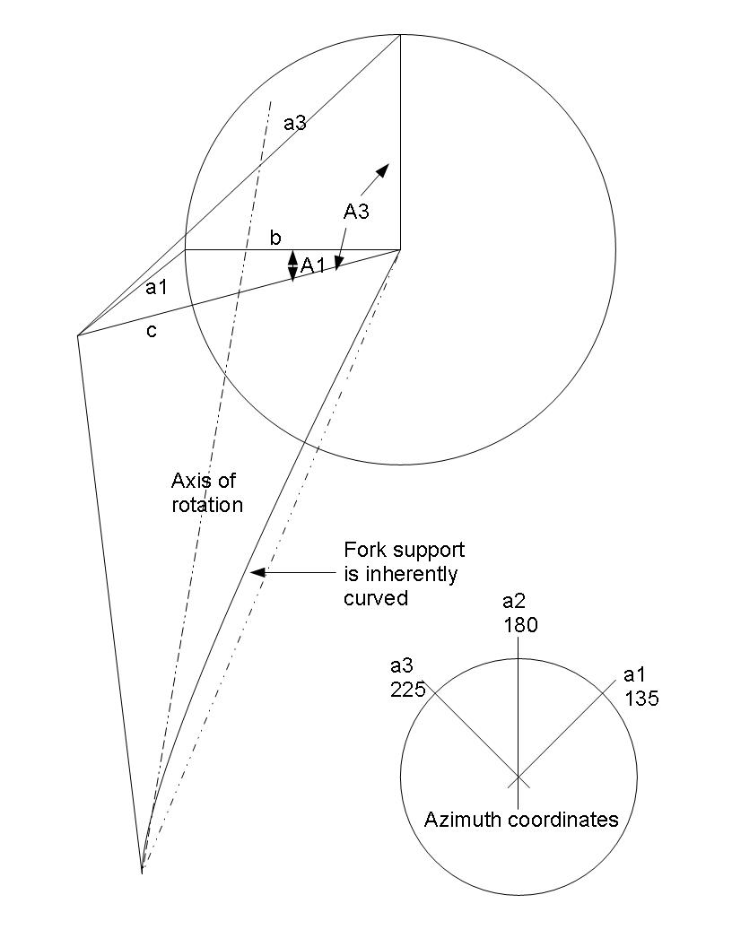
The first issue to be considered is the ideal location of the linear actuator for the desired range of motion. Secondly, but most importantly: the resultant equation of motion so that the miror angle may be calculated based on the actuator position.
Lets define the range of motion:
Altitude Axis - the altitude axis only goes from 0 to 90, and the bisecting angle would only need a range of 45; however a couple of special positions need to be kept in mind: park, and clean. A park position pointed straight up should generally avoid having the reflection go in an unwanted direction (at least for typical residential applications). The resulting horizontally level position makes an easy way of calibrating the position. Likewise, having a cleaning position which puts the mirrors in a vertical orientation not only facilitates maintenance, but also provides another crucial calibration point. Knowing the desired range of rotation, and the range of motion the linear actuator is capable of, we can calculate the ideal radius (b) of the actuator fulcrum (C), as well as the position of the actuator base(B). This defines two sides of a triangle. Side c remains completely fixed, while side (b) remains fixed in length, but pivots about point (A), as required by changes in the value of side (a). The law of cosines, which states that the ratios of the sides and the cosine of their respective angles are equal, lets us solve the angle (A) based on the known sides.
|
